Industrial-Grade Animal Fat Primary Rendering
Explore MoreFood-Grade Animal Fat Primary Rendering
Explore MoreControlling odor and emissions in an animal fat rendering plant requires a layered treatment train: condensers capture steam-phase organics, cyclone separators remove airborne dust, and wet scrubber towers neutralize the soluble gases that cause odor complaints and regulatory violations. When these three systems are correctly sized and sequenced, a rendering facility can meet strict local emission limits while protecting community relations and operating licenses. The sections below explain how each technology works, how they integrate, and what compliance strategies experienced operators use to stay ahead of inspections.
| Criteria | Wet Scrubber Tower | Cyclone Dust Separator | Shell-and-Tube Condenser |
|---|---|---|---|
| Primary function | Absorbs soluble gases (H₂S, NH₃, VOCs) | Removes particulate dust from exhaust air | Condenses steam and recovers volatile organics |
| Target pollutant | Odorous gases and acid/alkaline compounds | Bone meal dust and fine particulates | Water vapor and light hydrocarbons |
| Typical placement in line | Final stage before stack discharge | After dryer or cooker exhaust duct | Between cooker/dryer and scrubber inlet |
| Operating medium | Caustic soda or acid solution | None — dry centrifugal separation | Cooling water circuit |
| Maintenance frequency | Weekly nozzle inspection; monthly packing check | Monthly hopper cleanout | Quarterly tube-side flush |
| Odor removal efficiency | 85–98% for soluble compounds | Low — targets particulates, not gases | Moderate — reduces vapor load upstream |
Animal by-products contain proteins, fats, and moisture that release a complex mixture of volatile organic compounds (VOCs), hydrogen sulfide (H₂S), ammonia (NH₃), and mercaptans when heated during cooking and drying. A single batch cooker in a chicken rendering plant processing 5 tonnes of poultry offal can exhaust gases with H₂S concentrations above 50 ppm and particulate loads exceeding 200 mg/Nm³ — both well above typical regulatory thresholds.
The two main emission sources are:
Understanding which source dominates at your facility determines which treatment equipment to prioritize and size first. Plants processing ruminant material typically face heavier H₂S loads; poultry plants often see higher ammonia and particulate levels.
Effective emission control in a rendering plant is not a single device — it is a sequential treatment train where each stage reduces the load on the next. Skipping or undersizing any stage forces the final stack to carry pollutants it cannot handle alone.
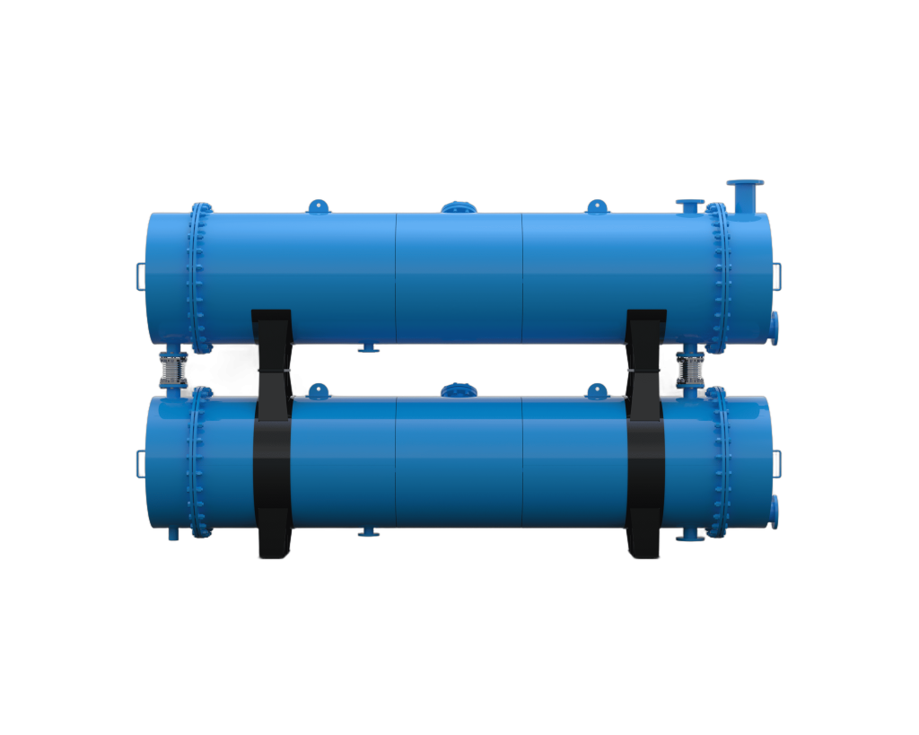
Exhaust gases from the cooker and dryer first pass through a shell-and-tube condenser, where cooling water drops the gas temperature from roughly 90–110 °C to below 40 °C. This condenses the bulk of the steam and recovers water-soluble organics as condensate, reducing the volumetric gas flow to the downstream scrubber by 60–75% and dramatically cutting the scrubber's chemical consumption.
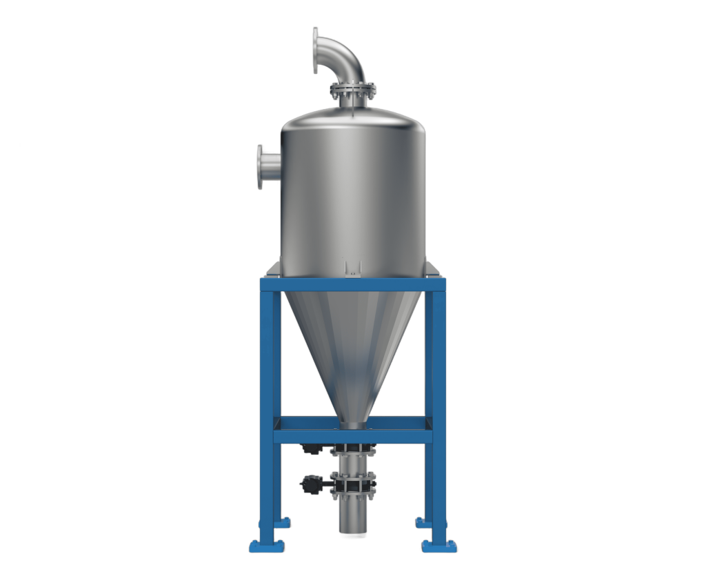
Meal-handling exhaust and any particulate-laden air from the dryer outlet pass through a cyclone dust separator before entering the scrubber. Centrifugal force drives bone meal particles — typically 10–200 µm — to the hopper wall, achieving 85–95% collection efficiency for particles above 10 µm. Collected meal is returned to the production stream, recovering product value while protecting scrubber packing from blinding.
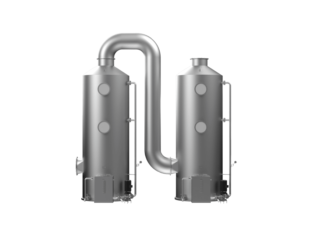
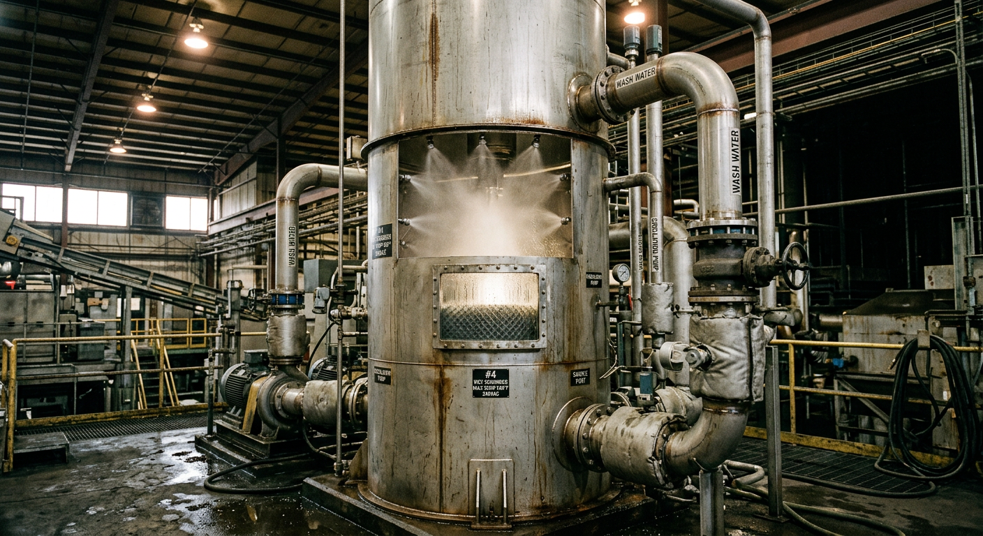
Pre-conditioned, dust-free gas enters the wet scrubber tower, where a counter-current spray of dilute caustic soda (NaOH, 2–5%) absorbs H₂S and acidic VOCs, while an acid wash stage (optional) targets ammonia. Well-designed scrubbers achieve 90–98% removal of soluble odorous compounds, bringing stack emissions within the limits set by most national environmental agencies.
Correct sizing is the most common failure point in rendering plant emission systems. Undersized equipment passes regulatory audits on paper but fails under peak production loads.
Calculate the maximum steam generation rate from your cooker at peak batch load. For a 3-tonne batch cooker operating at 130 °C, steam generation typically reaches 150–200 kg/h. The condenser heat-transfer area must be sized to handle this peak load with a 20% safety margin.
Cyclone inlet velocity should be maintained between 15–20 m/s for optimal separation efficiency. Too slow and particles pass through; too fast and turbulence re-entrains collected dust. For plants producing more than 2 tonnes/h of meal, a multi-cyclone bank in parallel is more effective than a single large unit.
Scrubber tower diameter is determined by the post-condenser gas volume flow rate. A superficial gas velocity of 1.0–1.5 m/s through the packing bed is the standard design target. Packing height of 2–3 metres of structured polypropylene packing is typical for rendering applications. Chemical dosing pumps should be interlocked with the cooker and dryer start signals so scrubbing solution is always circulating before exhaust gases arrive.
For a detailed look at how these systems integrate into a full facility layout, see our guide on designing the layout of an animal fat rendering plant.
A practical illustration of how this treatment train performs at scale comes from Liande's Malaysia 80-tonne daily slaughter waste treatment project. The facility processes mixed poultry and livestock by-products, generating significant exhaust gas volumes from multiple batch cookers running in staggered cycles throughout the day.
The installed waste gas system included:
The key operational lesson from this project: staggering cooker batch start times by 45 minutes reduced peak gas flow to the scrubber by 35%, allowing a smaller scrubber to be specified without compromising compliance — a significant capital cost saving for the client.
Installing the right equipment is necessary but not sufficient. Rendering plant operators who maintain compliance long-term follow structured operational protocols alongside their hardware investments.
Install fixed H₂S and NH₃ sensors at the scrubber stack outlet and log readings automatically. Many regulators now require continuous emissions monitoring (CEM) data for annual permit renewals. Real-time data also alerts operators to scrubber chemical depletion before a violation occurs.
Keep the entire raw material receiving area, cooker hall, and meal handling zone under slight negative pressure (–5 to –10 Pa relative to atmosphere) by connecting all enclosures to the waste gas treatment ducting. This prevents fugitive odors from escaping through doors and access panels — the most common source of neighbor complaints.
Scrubber nozzles should be inspected weekly for blockage; cyclone hoppers cleared at least monthly; condenser tubes flushed quarterly to prevent fouling from fat deposits. A blocked nozzle in the scrubber can reduce absorption efficiency by 30–40% within a single shift.
Maintain scrubbing solution pH between 9 and 11 for caustic wash stages. Install automatic pH dosing controllers rather than relying on manual addition — pH drift is the single most common cause of scrubber underperformance in rendering plants.
For a broader view of how emission control fits into the full rendering process, our industrial guide to batch and continuous animal fat rendering provides useful process context. You can also explore Liande's complete waste gas treatment equipment range to review system configurations for different plant capacities.
Liande Machinery engineers complete rendering lines with integrated emission control systems — from condenser to cyclone to scrubber — sized and specified for your raw material throughput and local regulatory requirements. Contact our engineering team to discuss a waste gas treatment solution for your facility.
 Industry Success Case
 Industry Success Case
 Industry Success Case
 Industry Success Case
 Industry Success Case

Chinese (Simplified)

English

Russian