Industrial-Grade Animal Fat Primary Rendering
Explore MoreFood-Grade Animal Fat Primary Rendering
Explore MoreDesigning an animal fat rendering plant layout requires aligning three interdependent variables: daily raw material throughput, a logical process flow that minimizes cross-contamination and material handling distance, and compliance with local environmental and food-safety regulations. Get these three elements right from the start, and your facility will operate efficiently, scale predictably, and pass regulatory inspections without costly retrofits. The sections below walk through each design dimension with specific engineering guidance.
| Criteria | Batch Rendering Layout | Continuous Rendering Layout |
|---|---|---|
| Ideal throughput | 5–50 tonnes/day | 50–500+ tonnes/day |
| Floor space requirement | Compact, modular | Linear, larger footprint |
| Capital investment | Lower upfront cost | Higher upfront cost |
| Operational flexibility | High — handles mixed species | Lower — optimized for single stream |
| Automation level | Semi-automated | Fully automated |
| Best for | Slaughterhouses, small processors | Large rendering facilities, integrators |
Every layout decision flows from one number: tonnes of raw material processed per day. Underestimate it and you bottleneck the line within two years; oversize it and capital sits idle. A reliable capacity figure comes from three inputs — slaughter volumes (current and projected), by-product yield percentage by species, and planned operating hours per shift.
Once daily tonnage is confirmed, size the batch cooker or continuous cooker as the rate-limiting anchor point, then size every upstream and downstream unit to match that throughput with a 10–15% buffer. For a detailed cooker sizing methodology, see our guide on how to size and select a batch cooker for your rendering plant.
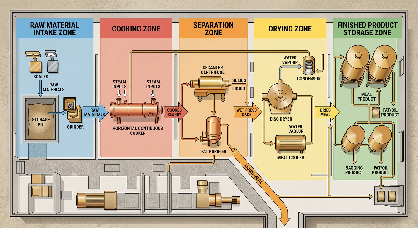
A rendering plant layout is essentially a physical map of the process sequence. Raw material must travel in one direction — from dirty intake to clean finished product — without backtracking or crossing contaminated zones. The standard flow for a wet-rendering or dry-rendering line follows this sequence:
Divide the plant floor into three clearly demarcated zones: raw (red zone), processing (amber zone), and finished product (green zone). Personnel, equipment, and airflow should never move from red to green without passing through a transition point. This single design rule prevents cross-contamination and satisfies most food-safety audit requirements.
For instance, a Malaysian slaughterhouse processing 80 tonnes of mixed poultry and cattle waste daily structured their layout around a central cooking hall flanked by a raw intake bay on the north side and a separation/drying hall on the south — a configuration that kept raw and finished product streams physically separated by a full building section. See the full project profile: Malaysia's 80-ton daily slaughter waste treatment project.
The choice between batch and continuous rendering fundamentally changes the plant footprint and equipment arrangement. Batch systems are modular and compact — ideal for processors handling 5–50 tonnes per day or facilities running mixed species. Continuous systems demand a linear, larger-footprint layout but deliver higher throughput and lower per-tonne operating costs above 50 tonnes/day.
The comparison table above summarizes the key trade-offs. For a deeper technical breakdown of each method, refer to our industrial guide to batch and continuous animal fat rendering processes.
A Shandong meat and bone meal producer running 120 tonnes/day opted for a continuous layout with a 90-meter processing hall, achieving a 22% reduction in labor cost per tonne compared to their previous batch operation. Details are documented in the Shandong Minsheng meat and bone meal and animal fat project.
Once the process flow is fixed, the engineering team must overlay three utility systems: steam, electrical, and drainage. Mistakes in utility routing are the most common cause of costly mid-construction redesigns.
Batch cooker, disc dryers, and heating buffer tanks all require saturated steam. Place the steam main pipe above the processing floor on the elevated pipe rack, and do not bury it in areas where leaks cannot be detected.
Batch cookers loaded with raw material can exceed 8–12 tonnes per unit. Disc dryers and centrifuges generate significant vibration. Specify reinforced concrete slabs rated for dynamic loads in the processing zone — typically 10–15 kN/m² minimum — and isolate vibrating equipment on inertia bases.
All drains in the raw and processing zones must slope to a central collection sump with a grease trap before connecting to effluent treatment. Design drain channels wide enough (minimum 200 mm) to handle wash-down volumes without backing up during cleaning cycles.
Rendering plants generate non-condensable gases (NCGs) and odorous vapors during cooking and drying. Regulators in most jurisdictions — including EU Regulation 1069/2009, USDA guidelines, and equivalent standards across Southeast Asia — require that all process exhaust be treated before discharge. Failure to design this system into the original layout is the single most common compliance failure in new rendering facilities.
Position the waste gas treatment train at the end of the processing hall, with dedicated ductwork connecting each cooking and drying unit. Duct runs should be as short and straight as possible to minimize pressure drop and condensate accumulation. Budget 80–120 m² of floor space for a complete waste gas treatment system serving a 50-tonne/day plant.
Design exhaust duct manifolds with spare branch connections sized for 30% additional capacity. Adding a cooker or dryer later should never require cutting new holes in the building envelope — a lesson learned the hard way by many expanding operators.
 Industry Success Case
 Industry Success Case
 Industry Success Case
 Industry Success Case
 Industry Success Case

Chinese (Simplified)

English

Russian